Technical Specifications
Block Diagram
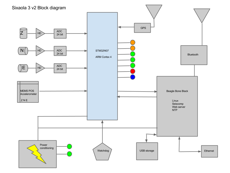
Note that in Sixaola4, the MEMS sensors have been replaced by OSOP’s GeoFlex sensor
It is really very simple, don’t you think?!
The velocity sensors are 4.5 Hz geophones electronically extended to 0.5 Hz then digitized with an ADS1281 24 bit instrument-grade digitizer. The data flows into an ARM Cortex4 procesor where the data is time stamped. There are also three channels of MEMS acelerometer data.
Power input is 9 volts and that is highly protected and conditioned.
The GPS is a LINX module which needs to see five satellites to acquire Lock status. See Timing for more details.
The computer is a BeagleBone Black (BBB) which is connected to the STM32 and to a bluetooth reciever. The computer runs Debian Linux (see Operating system for more details). Attached to the BBB is a USB which serves as the storage when the Sixaola is configured in Trigger Logger or Data Logger Modes (see Data Flow Mode for more details).
A PIC runs a watchdog which monitores several processes and issues a reboot if needed.
Instrument Response
The Sixaola has a flat frequency response from ~0.5 Hertz (2 seconds) to 80% Nyquist:
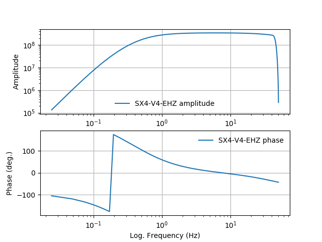
Sixaola velocity channel instrument response
For more details: Click here to download the technical specifications sheet for Sixaola4-V2.
For more details: Click here to download the technical specifications sheet for Sixaola3-V2.
Download the instrument response
You can download the complete instrument response in dataless and RESP formats directly from your Sixaola (station name, sample rates, latitude, longitude, elevation are automatically populated):
Open the web interface >> sign in >> navigate to Instrumentation >> Click the “Download instrument response” button.
SX4-V4:
Self-Noise
See also: ASL report
OSOP designed the Sixaola for local and regional earthquake detection.
Below we compare the self-noise for 3 co-located Sixaola short-period seismometers using the Sleeman method. The New High- and Low- Noise Models (NHNM, NLNM) from Peterson, 1993 and earthquake models for local and regional events from Clinton and Heaton, 2002 are plotted for comparison.
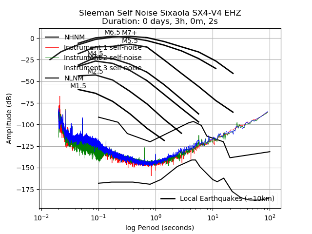
Sixaola self-noise compared to local seismicity
References:
Clinton, J.F. and Heaton, T.H. (2002) Potential advantages of a strong-motion velocity meter over a strong-motion accelerometer, Seismological Research Letters 73: 338 pp.
Peterson, J. (1993) Observations and modeling of seismic background noise, USGS Open-File Report 93-322: 95 pp.
Sleeman, R., van Wettum, A., Trampert, J. (2006) Three-channel correlation analysis: A new technique to measure instrumental noise of digitizers and seismic sensors. Bulletin of the Seismological Society of America 96: 258-271.
Technical Specifications Sheet
Click here to download the technical specifications sheet for Sixaola4-V2.
Click here to download the technical specifications sheet for Sixaola3-V2.
See also:
Input Voltage Requirements
Warning
Pay special attention here if you are using a solar system and be sure to set your float properly so that the Sixaola does not reset
Sixaola4-V2+
| Voltage in | Description |
|---|---|
| < 8.3v | Power completely removed |
| 8.3 to 8.5 | Hysterisis zone Power removed when input voltage falls below 8.3v. Enter reset mode when input voltage increases above 8.5v. |
| 8.5 to 9.7 | Reset active. |
| 9.7 to 10.8 | Hysterisis zone. Reset gets taken away when input voltage increases above 10.8v. Reset gets applied again when input voltage falls below 9.7v. |
| 9.7 to 16.5 | Running. |
| 15.5 to 16.5 | Hysterisis zone. Reset applied when input voltage increases above 16.5v. Reset removed when input voltage decreases below 15.5v. Enter reset mode when power falls from above 17v to 16.1v. |
| 16.5 to 17 | Reset active. |
| 17 to 220 | Power completely removed. |
Sixaola4-V2: Input Voltage Behavior
Sixaola3-V2 (post-Sept, 2015)
| Voltage in | Description |
|---|---|
| < 9v | Power completely removed |
| 9 to 9.4 | Hysterisis zone Reset applied when input voltage falls below 9.5v. Enter reset mode when input voltage increases above 9.4v. |
| 9.4 to 9.9 | Reset active. |
| 9.4 to 10.7 | Hysterisis zone Reset gets taken away when input voltage increases above 10.7v. Reset gets applied when input voltage falls below 9.9v. |
| 9.9 to 15.1 | Running. |
| 14.6 to 15.1 | Hysterisis zone. Reset applied when input voltage increases above 15.1v. Reset removed when input voltage decreases below 14.6v. |
| 15.1 to 15.9 | Hysterisis zone. |
| 15.9 to 220 | Power completely removed. |
Sixaola3-V2 (post-Sept, 2015): Input Voltage Behavior
Sixaola3-V2 (pre-Sept, 2015)
| Voltage in | Description |
|---|---|
| < 9v | Power completely removed |
| 9 to 9.4 | Hysterisis zone. Reset applied when input voltage falls below 9.5v. Enter reset mode when input voltage increases above 9.4v. |
| 9.4 to 10.7 | Hysterisis zone (*). Reset gets taken away when input voltage increases above 10.7v. Reset gets applied when input voltage falls below 9.5v. |
| 9.5 to 14.5 | Running. |
| 14.2 to 14.5 | Hysterisis zone. Reset applied when input voltage increases above 14.5v. Reset removed when input voltage decreases below 14.2v. |
| 14.5 to 15.1 | Reset active. |
| 15.1 to 15.8 | Hysterisis zone. |
| 15.8 to 220 | Power completely removed. |
(*) CAUTION: When increasing the voltage from 10.1 to 10.7 volts, the Sixaola could enter a state of a infinite reset loop if the power hovers in this range.
Sixaola3-V2 (pre-Sept, 2015): Input Voltage Behavior