
Raspberry Jam (RJAM) Universal Digitizer#
Contents
Raspberry Jam (RJAM) Universal Digitizer
-
Recommended component values for active sensors with 40V Differential outputs
Recommended component values for active sensors with 20V Differential outputs
Recommended component values for active sensors with 10V Differential outputs - FBA23 specific*
Recommended component values for geophones (passive sensors, not powered)
Manual#
Note
All models of Raspberry Shake, including the RS1D, RS3D, RS4D, RBOOM, RS&BOOM and RJAM use the same software. Sections of the Quick Start Guide have been tailored to each product but the overall manual applies to them all. Other specific manual sections, like this one, have been created to address issues specific to the individual products.
Technical Specifications Documents#
Raspberry Jam Universal Digitizer (RJAM) Technical Specifications Sheet
Note
Unlike other Shake products, the RJAM has no long period extension (from 4.5 Hz to ~2 seconds) as this would be undesirable for and incompatible with active sensors.
For details on the RJAM’s instrument response, see: Raspberry Shake RJAM
Design and Customization#
Note
The RJAM was discontinued in late 2021.
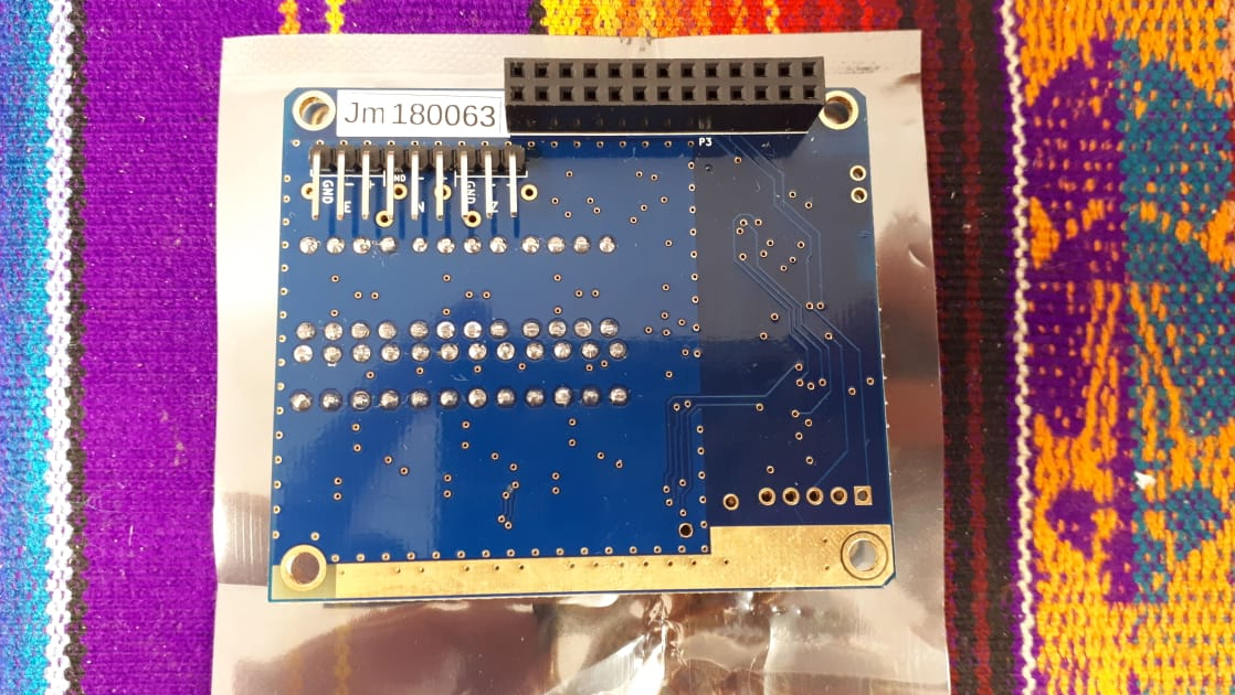
The RJAM digitizer was designed to work with most seismic sensors and supports 3-channels of single-ended and differential-ended signal inputs, passive and active sensors. Though, with single-ended inputs, one looses half the dynamic range.
Through-hole mountings are provided for resistors and capacitors to make it easy for electronics engineers and power users/ Do-It-Yourselfers to swap out components. The system is highly customizable for any sensor that has an output between +/-2.5 Volt absolute referenced to ground (also called 10 Volt differential) to +/-10 Volt absolute referenced to ground (also called 40 Volt differential).
Warning
The RJAM board is ESD sensitive, and ESD precautions must be taken when soldering components and hooking up sensors. Even small ESD events can damage the response of the RJAM and cause small signal accuracy or reliability issues, both of which are difficult to detect but cause signal distortion. Also, be sure to populate the card with the appropriate resistors and capacitors BEFORE hooking up any sensors.
Warning
Like any digitizer not inside of a metal enclosure, you should be careful with any RF sources in the area.
Channels (as labelled on PCB board):
Channel # |
Resistors |
Capacitors |
|---|---|---|
1 |
R13,R14,R15,R16,R24 |
C29,C30,C31,C32 |
2 |
R22,R34,R35,R37.R38 |
C23,C24,C58,C59 |
3 |
R30,R52,R53,R55,R56 |
C33,C34,C62,C63 |
Component Groups:
Group |
Sensor Type |
Components |
|---|---|---|
R[damp] |
Passive with signal output 0 - 3 Volts |
Damping (“Shunt”) Resistors: R22,R24,R30 |
R[a] |
Active/ Passive with signal output >3V |
R13,R14,R35,R37,R53,R55 |
R[b] |
Active/ Passive with signal output >3V |
R15,R16,R34,R38,R52,R56 |
C[a] |
Any, optional |
LP Filter Capacitors: C23,C29,C31,C33,C59,C63 |
C[b] |
Any, optional |
LP Filter Capacitors: C24,C30,C32,C34,C58,C62 |
Note
Filter capacitors C[a] and C[b] are optional and can be included to provide, for example, a single-pole low-pass filter at 50 Hz. Filter capacitors were included in board design to provide some minimal protection to keep 50/60 Hz electrical noise out of the system. This low-pass filter is followed by a multiple pole digital LPF with a -3 dB frequency at ~40 Hz. The capacitor selected is best if it is a film type capacitor. If a ceramic capacitor is used, make sure it is rated at 25V or above. Do not use polarized capacitors. For film capacitors, use any type with a voltage rating above 10 volts.
Recommended component values for active sensors with 40V Differential outputs#
Group |
Components |
Part Value |
Manufacturer Part # |
Digikey Part # |
|---|---|---|---|---|
R[damp] |
Damping Resistors (Optional): R22,R24,R30 |
Do not include |
Do not include |
Do not include |
R[a] |
R13,R14,R35,R37,R53,R55 |
33kOhm, 0.1%, 1/8Watt, 25ppm |
MFP-25BRD52-33K |
33KADCT-ND |
R[b] |
R15,R16,R34,R38,R52,R56 |
12kOhm, 0.1%, 1/4Watt, 25ppm |
MFP-25BRD52-12K |
12KADCT-ND |
C[a] |
LP 50 Hz Filter Capacitors: C23,C29,C31,C33,C59,C63 |
0.47uF, 5%, 63VDC |
R82DC3470SH60J |
399-11865-1-ND |
C[b] |
LP 50 Hz Filter Capacitors: C24,C30,C32,C34,C58,C62 |
0.22uF, 5%, 40VDC |
R82DC3220AA60J |
399-9686-ND |
As most active sensors on the seismology market have output voltages of 40V Differential, resistors for this input range are specified above. If you have a non-40V special case, email us and we will send you the appropriate resistor values.
This configuration is for sensors with a differential output resistance of 500 ohms or less. It is unusual for active sensors to have higher output resistance. A higher output resistance will cause a decrease in available dynamic range.
This configuration gives a differential input resistance of about 100 kOhms. High sensor output impedance will cause a corresponding gain reduction.
Recommended component values for active sensors with 20V Differential outputs#
Group |
Components |
Part Value |
Manufacturer Part # |
Digikey Part # |
|---|---|---|---|---|
R[damp] |
Damping Resistors (Optional): R22,R24,R30 |
Do not include |
Do not include |
Do not include |
R[a] |
R13,R14,R35,R37,R53,R55 |
20kOhm, 0.1%, 1/8Watt, 25ppm |
MFP-25BRD52-20K |
20KADCT-ND |
R[b] |
R15,R16,R34,R38,R52,R56 |
330Ohm, 0.1%, 1/4Watt, 25ppm |
MFP-25BRD52-330R |
330ADCT-ND |
C[a] |
LP 50 Hz Filter Capacitors: C23,C29,C31,C33,C59,C63 |
0.68 uF, 5%, 50VDC |
MKS2B036801C00J |
1928-1624-ND |
C[b] |
LP 50 Hz Filter Capacitors: C24,C30,C32,C34,C58,C62 |
100 nF, 5%, 63VDC |
R82DC3100DQ50J |
399-5444-1-ND |
The above configuration is for sensors with a differential output resistance of 250 ohms or less. It is unusual for active sensors to have higher output resistance. A higher output resistance will cause a decrease in available dynamic range.
This configuration gives a differential input resistance of about 50 kOhms. High sensor output impedance will cause a corresponding gain reduction.
Recommended component values for active sensors with 10V Differential outputs - FBA23 specific*#
Group |
Components |
Part Value |
Manufacturer Part # |
Digikey Part # |
|---|---|---|---|---|
R[damp] |
Damping Resistors (Optional): R22,R24,R30 |
Do not include |
Do not include |
Do not include |
R[a] |
R13,R14,R35,R37,R53,R55 |
4.99kOhm, 0.1%, 1/4Watt, 15ppm |
H84K99BYA |
A105672-ND |
R[b] |
R15,R16,R34,R38,R52,R56 |
2.20kOhm, 0.1%, 1/4Watt, 25ppm |
MFP-25BRD52-2K2 |
2.2KADCT-ND |
C[a] |
LP 58 Hz Filter Capacitors: C23,C29,C31,C33,C59,C63 |
0.68 uF, 5%, 50VDC |
MKS2B036801C00J |
1928-1624-ND |
C[b] |
LP 58 Hz Filter Capacitors: C24,C30,C32,C34,C58,C62 |
0.22 uF, 5%, 40VDC |
R82DC3220AA60J |
399-9686-ND |
This configuration gives a differential input resistance of about 25 kOhms.
(*) Or any active sensor that has a 1000 Ohm differential output impedance. This configuration won’t give good results for any sensor with a different output impedance. If used with sensors that have a different output resistance, the input dynamic range will be affected.
Recommended component values for active sensors with 10V Differential outputs - Episensor FBA ES-T specific*#
Group |
Components |
Part Value |
Manufacturer Part # |
Digikey Part # |
|---|---|---|---|---|
R[damp] |
Damping Resistors (Optional): R22,R24,R30 |
Do not include |
Do not include |
Do not include |
R[a] |
R13,R14,R35,R37,R53,R55 |
2.67kOhm, 0.1%, 1/4Watt, 15ppm |
RNF14BTE2K67 |
RNF14BTE2K67CT-ND |
R[b] |
R15,R16,R34,R38,R52,R56 |
Same as R[a] |
Same as R[a] |
Same as R[a] |
C[a] |
LP 52 Hz Filter Capacitors: C23,C29,C31,C33,C59,C63 |
0.68 uF, 5%, 50VDC |
MKS2B036801C00JSSD |
1928-1624-ND |
C[b] |
LP 52 Hz Filter Capacitors: C24,C30,C32,C34,C58,C62 |
0.33 uF, 5%, 63VDC |
R82DC3330AA60J |
399-5906-ND |
This configuration gives a differential input resistance of about 20.8 kOhms though any active output sensor will be able to drive this.
(*) Kinemetrics EpiSensor FBA ES-T or any active sensors with 2 * 50 Ohm or less (differential) output impedance and an output of +/-5V differential (10V differential)
Note
According to Kinemetrics, the EpiSensor output voltage levels are user-selectable at either ±2.5V or ±10V single-ended, or +/- 5V or +/- 20V differential. The RJAM does not support the single-ended outputs. What Kinemetrics refers to as “+/-5V differential output” is understood here, and in the electronics world, as “10V Differential”. Similarly, “”+/-20V differential output” is unstood here as “40V differential”. We recommend the 40V differential- for this see “Recommended component values for active sensors with 40V Differential outputs” (above). If you use the configuration specified here for 10V Differential outputs, make sure that “Headers” (jumpers) X9,X14,X19 are set to outputs 1-2 as seen here: Episensor FBA ES-T.
Recommended component values for active sensors with an absolute output voltage span of 3 volts or less#
Group |
Components |
Part Value |
Manufacturer Part # |
Digikey Part # |
|---|---|---|---|---|
R[damp] |
Damping Resistors: R22,R24,R30 |
Do Not Install |
||
R[a] |
R13,R14,R35,R37,R53,R55 |
0 Ohm (shorted) |
||
R[b] |
R15,R16,R34,R38,R52,R56 |
0 Ohm (shorted) |
||
C[a] |
C23,C29,C31,C33,C59,C63 |
Do Not Install |
Do Not Install |
Do Not Install |
C[b] |
C24,C30,C32,C34,C58,C62 |
Do Not Install |
Do Not Install |
Do Not Install |
This configuration gives a differential input resistance of about 10.2 kOhms. High sensor output impedance will cause a corresponding gain reduction.
Recommended component values for geophones (passive sensors, not powered)#
Group |
Components |
Part Value |
Manufacturer Part # |
Digikey Part # |
|---|---|---|---|---|
R[damp]* |
Damping Resistors: R22,R24,R30 |
Execute program |
||
R[a]* |
R13,R14,R35,R37,R53,R55 |
Execute program |
||
R[b]* |
R15,R16,R34,R38,R52,R56 |
Execute program |
||
C[a] |
LP Filter Capacitors: C23,C29,C31,C33,C59,C63 |
Execute program |
||
C[b]** |
Use for resistors C24,C32,C34 |
1 MOhm, 0.5%, 1/4Watt, 25ppm*** |
YR1B1M0CC |
A105943CT-ND |
C[b] |
C30,C58,C62 |
Do not install |
(*) Resistors must be 25ppm or less.
(**) Install resistors at these capacitor locations.
(***) Resistor value can be anything between 950 kOhm and 1 MOhm, but must be 25ppm or less.
You will need to run this bit of Python code: RJAM Passive Sensors Calculated. Dependecies include python, python-tk, python-numpy.
The program will ask for the critical damping resistance or shunt resistance of the geophone being used. This resistance (sometimes called the CDR for “critical damping resistance”, “shunt resistance” or just “damping resistor”) depends on how much damping one wants. The CDR is the maximum allowed to avoid the sensor ‘ringing’ after a step stimulus. The CDR is the value of shunt resistor required to get a damping factor of 1. For example, for the Teledyne Geotech S-13 passive geophone, the manual says that for a critically damped 102a-type coil with a Resistance per winding of 3.600 kOhms and a natural frequency of 1 Hz, the CDR is 6.525 kOhms (though the actual value is sensor specific and was provided with the sensor at the time of purchase).
Warning
We do not recommend the RJAM for any small passive geophones with generator constants below about 55 V/m/s. Use the RS1D or RS3D instead. More than half the possible dynamic range is lost when using low generator constant geophones with the RJAM.
Common valued capacitors to use#
Value |
Manufacturer Part # |
Digikey Part # |
Mouser Part # |
|---|---|---|---|
1uF |
MKS2B041001C00JSSD |
505-MKS2B041001C00JS |
|
0.68uF |
MKS2B036801C00JSSD |
1928-1624-ND |
|
0.47 uF |
R82DC3470SH60J |
399-11865-1-ND |
|
0.33uF |
R82DC3330AA60J |
399-5906-ND |
|
0.22uF |
R82DC3220AA60J |
399-9686-ND |
|
0.1uF |
R82DC3100DQ50J |
399-5444-1-ND |
Examples#
Passive Sensors#
Examples of passive sensors that RJAM is compatible with:
Manufacturer |
Sensor |
Notes |
|---|---|---|
Many |
Geophones |
WARNING: We do not recommend the RJAM for small, low generator constant (e.g., 28.8 V/m/s) geophones. Use the RS1D or RS3D instead. |
Kinemetrics |
SS-1 Ranger |
|
Sercel |
L-4C |
previously Mark Products |
Teledyne Geotech |
S-13 GS-13[BH] GS-21 |
Active sensors#
The RJAM is compatible with the following active sensors and many more:
Manufacturer |
Sensor |
Known* Differential Voltage** |
Notes |
|---|---|---|---|
Chaparral |
Model [25,25/21] Model 50 Model 50a Model 60/64; 60Vx Model 60UHP |
– – – – – |
None Assuming 40V pk-pk Diff. output; data sheet is inconclusive None Sensor is 44V pk-pk Diff. When used with 40V pk-pk Diff input, signal will clip at ~90% of sensor’s full-scale 36V pk-pk Diff. actual. Use 40V Diff input. |
GeoSIG |
AC-23 |
– |
20V pk-pk Diff. |
Geotech |
KS-[1,2000,5400] PA23 S-230 S-13 and other passive sensors |
– – – – |
None Assuming 40 V differential output Assuming 40 V differential output See previous table |
Guralp |
[3,5T,6,6T,40] Series Fortis |
– – |
None None |
Kinemetrics |
Episensor [2,ES-T,ES-U2] HypoSensors (FBA ES-DH) FBA23 SBEPI (202) |
10,40 – 10 – |
See above “Recommended component values for active sensors with 10V Differential outputs - Episensor FBA ES-T specific” None See above “Recommended component values for active sensors with 10V Differential outputs - FBA23 specific” None |
Lennartz |
LE-3D[lite/5s] MKIII |
– |
40V input comes close though the dynamic range is reduced. Better would be a 30V input range. |
Metrozet |
MBB-[1/2] PBB-200H |
– 40 |
None None |
Nanometrics |
Trillium Compact[PH,AT] Trillium 120[Q/QA] Titan |
40 40 40 |
None None None |
RefTek (Trimble) |
151B-120 147A |
– – |
None None |
Seismowave |
LP[ZA,HA] MB3 A |
– – |
Assume output is 40V pk-pk Diff., but would be probably better served with a 50V pk-pk Diff. input structure. Assume output is 40V pk-pk Diff., but would be probably better served with a 50V pk-pk Diff. input structure. |
Steckeisen |
STS[2,2.5,5A,6A] |
– |
Unsure what output level actually is. Assume output is 40V pk-pk Diff., but would be probably better served with a 50V pk-pk Diff. input structure. |
(*) Known = we have tested them in the lab
Note
(**) We assume that, in the seismology world, “40V peak-to-peak differential” output means that the output voltage of each signal line is swinging +/- 10 Volts with respect to ground. We have made this example list with that definition in mind, though it seems that in the seismology world the manufacturers are not consistent with how they specify the output level. In the end, the client is responsible for researching the solution and removing ambiguity surrounding how the manufacturer of their sensor(s) define the output level.
Note
Active sensors must be externally powered.
Special cases#
FMES DIY seismograph#
There is more than one configuration of the FMES circuit board out there. If you have the FMES 8.0 circuit board rev 1.7 (Bob LeDoux 12/30/2018) or equivalent, as shown here, then you might try with RJAM in the 40V-Differential configuration. Reducing the FMES output gain to 40x, by changing FMES board R25 from 4.99k to 200k, will correspondingly increase your dynamic range.
RJAM Cable diagram and connector specifications#
Raspberry Jam Universal Digitizer (RJAM) Cable Diagram Sheet
The RJAM DIY solution ships with a 9-pin male connector as shown below:
The female counterpart can be purchased on Digikey:
Contacts: Digikey WM2512-ND
Connector body: Digikey 23-0050579009-ND
Hand crimp tool: Molex 0638111000 (Digikey WM9999-ND) or equivalent
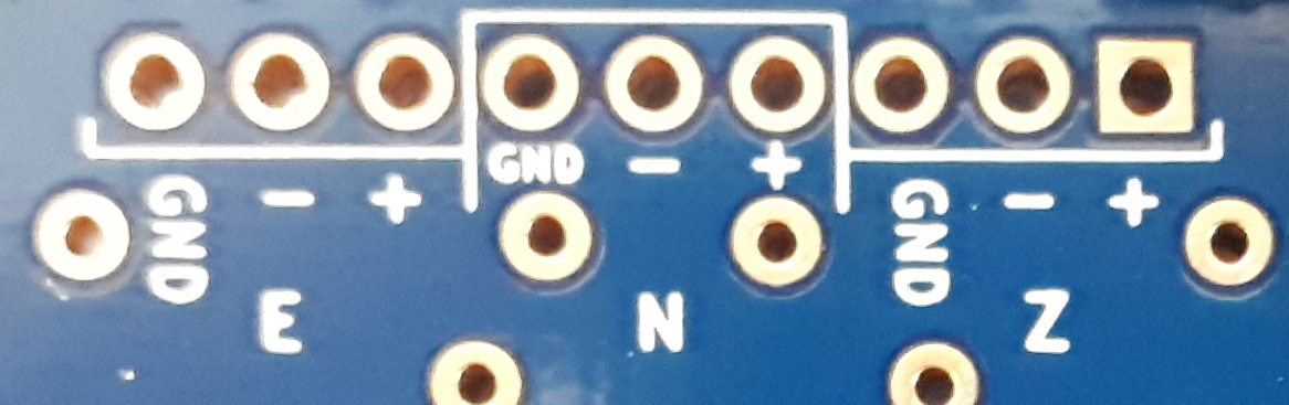
The sensor inputs (Z, N, E with +, -, and Ground) are shown on the back of the board underthe 9-pin connector as seen in the image below. The image is included here for reference in case your header covers up the labels.
The RJAM turn-key solution ships with an Amphenol PT07A-12-10S female connector. In addition to the sensor and cable, you will need to provide the male counterpart to this connector. We recommend the Amphenol PT06A-12-10P(SR). These are available on Mouser and Digikey.